The practical answer.
Use a single 25.6 V LiFePO4 pack if its operating window, current limits and enclosure fit the 24 V equipment and it simplifies service. Consider a pair of 12.8 V batteries only when the manufacturer explicitly allows series use for the exact model and documents the required protection and operating procedure. Compare both options as installed systems, with the same load, charge sources and recovery expectations.
- Two identical 12.8 V, 100 Ah units in series provide 25.6 V and 100 Ah in nominal arithmetic.
- Approval for parallel connection does not establish approval for series operation.
- Ask what the equipment will do when one member of a series pair reaches a protection threshold.
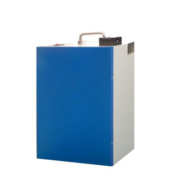
Translate the 24 V label into a topology and usable envelope
A 24 V label identifies a system class. The prepared Jetray series documentation distinguishes a 12.8 V nominal reference from a 25.6 V nominal example using eight 3.2 V nominal cells in series. The equipment owner still needs the charged and discharged terminal limits that the specific pack and system permit. The nominal number is the wrong value to enter as either the maximum charging voltage or the low-voltage operating boundary.
For an arithmetic comparison, two identical 12.8 V, 100 Ah units in series give 25.6 V at 100 Ah, or 2,560 Wh nominal. A single 25.6 V, 100 Ah pack has the same nominal energy on paper. In series the same load current passes through both units. A 40 A load flows through each unit at 40 A rather than being split between them. Delivered energy depends on the equipment cutoff, pack protection settings, temperature and how closely the units behave under load.
| Decision | One native 25.6 V pack | Two 12.8 V units in series |
|---|---|---|
| Topology approval | Check the pack operating envelope and equipment application | Obtain explicit series approval for exact units and their allowable combination |
| Capacity comparison | Read the approved pack capacity and test conditions | Series current flows through both units and the first to limit can end the run |
| Protection behavior | Request behavior of the pack and host as a single approved system | Request actions and recovery when either unit inhibits charge or discharge |
| Mechanical layout | Check one enclosure, terminal clearance and handling | Check two retention positions, interconnect routing and access to both units |
| Service and spares | Identify one full assembly replacement procedure | Identify allowed pairing, replacement and verification of both members |
Check the first unit to limit, especially during recovery
The system can stop while the sum of the two unit voltages still looks acceptable. One battery can reach its internal voltage or temperature boundary ahead of the other. If that member opens its discharge path, the equipment can lose the whole series source. Review whether the host saves state, sends a shutdown notification or cycles repeatedly when the source becomes available again.
During charge, a charger that reads only total voltage may have no direct view of unequal unit voltages. Ask the supplier how the intended system recognizes a blocked charge path and which equipment controls the restart. Confirm the permitted conditions for establishing a compatible pair at commissioning and after service. Internal balancing within each battery should never be taken as evidence that two separately protected units coordinate their state with each other.
Published manuals show why the model number matters. Victron describes bounded series use for one Lithium Smart range with its specified system equipment, while the Lithium SuperPack product documentation excludes series connection. Those examples illustrate manufacturer-specific decisions. They provide no permission for a Jetray model or any other product.
Compare the enclosure and spare-part policy together
One enclosure can simplify the wiring diagram. It can also require a larger access opening, a different mounting pattern or a heavier service lift. Two smaller enclosures may fit distinct approved locations, but the interconnect needs restraint, terminal protection and enough clearance for the specified assembly tools. Compare drawings with the real equipment covers and service routes in place.
Write a proposed spare-part rule before making a purchase. If one member of a pair needs replacement after years in service, ask whether the maker permits mixing production lots, ages or states of charge, and what evidence is required. If only paired replacement is permitted, budget for two modules and record that policy in the service manual. The decision may change when maintenance access and spares matter more than initial purchase cost.
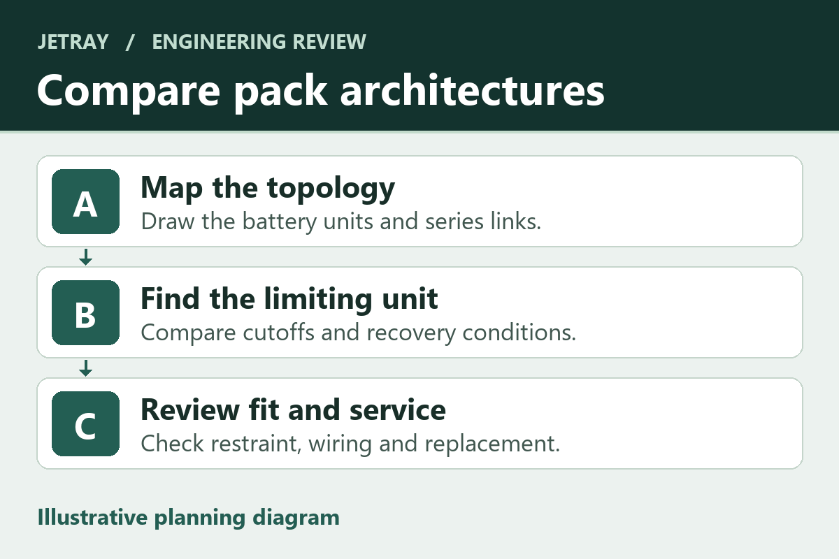
Prepare an equipment-level decision for purchasing
Use the linked 12 V class and 24 V class Jetray references to frame the supplier discussion. The two listed references illustrate product classes. For series authorization, charger settings and service procedures, request the current pack-specific documents.
- Record the equipment's allowed DC input window, load profile, cutoff behavior and all attached charging sources.
- Request the exact battery model, approved topology, maximum string scope and protection or recovery behavior from the supplier.
- Have the responsible system team review cable and protective device ratings against the entire installation and the manufacturer instructions.
- Compare fitted dimensions, access, replacement rules and spare inventory on the same system drawing.
- Write acceptance criteria for startup, shutdown and restoration before committing to the arrangement.
Questions to settle before choosing a 24 V architecture
Does two times 100 Ah become 200 Ah in series?
With equal 12.8 V, 100 Ah units connected in an approved series arrangement, the nominal voltage doubles while the nominal amp-hour rating remains 100 Ah. Actual available charge from the string is constrained by the first member or equipment limit.
May the equipment take a 12 V output from the midpoint?
A midpoint load can make the two members experience different energy use and alter the intended balance. Require an explicitly approved system design for the auxiliary output. A separately specified DC-DC supply is a common engineering approach to discuss with the equipment owner.
Sources & further reading
- Jetray LiFePO4 product categories and 4S/8S configuration examples ↗
- Victron Lithium Battery Smart installation manual, sections 4.5.1 to 4.5.5 ↗
- Victron Lithium SuperPack model-specific connection limits ↗
The 100 Ah energy comparison illustrates series arithmetic and does not identify an approved series pairing. Installation and commissioning use the applicable model's current instructions.
Prepared for the lifepo4 battery packs collection. General engineering guidance does not replace a model-specific datasheet or application validation. Source review: 5 November 2026.