The practical answer.
On the flat part of the LiFePO4 voltage curve, a small voltage uncertainty can hide a large SOC difference. Coulomb counting resolves short-term changes but accumulates current-sensor error. Validate usable capacity and the gauge’s recalibration conditions with pack data under the intended temperature, load and rest profile.
- A flat platform voltage makes open-circuit voltage a weak mid-band reference, so voltage correction must be gated to the sloping ends of the charge curve.
- Coulomb counting accumulates any current-sense offset until the pack sees a full charge, which is why partial cycling extends the interval in which LiFePO4 pack SOC estimation drift grows unchecked.
- Available capacity shifts with the temperature window and cycle life, making the denominator of a coulomb estimate a moving quantity rather than a fixed constant.
- Balancing current bypasses the main sensor; passive bleed and active transfer disturb the coulomb budget differently and should be declared in the BMS topology, alongside recalibration conditions confirmed per project.
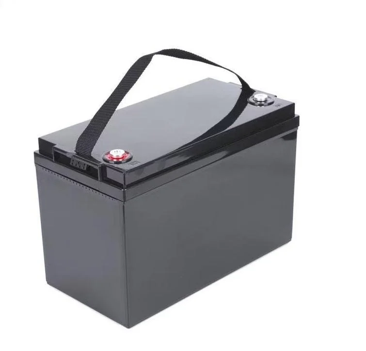
Decision context — lifepo4 pack soc estimation drift
An integration bench sits idle overnight. By morning the state-of-charge readout disagrees with the coulomb bookkeeping, although no load was drawn and no fault flag was raised. The pack voltage looks almost as it did the evening before. LiFePO4 pack SOC estimation drift is what makes that scene possible: a chemistry whose terminal voltage stays nearly flat across the middle of the charge curve. Where a sloping curve lets a BMS read state from voltage, a plateau leaves the estimator almost nothing to work with.
This is a parameter contradiction, not a broken part. The capacity the estimator divides by, the voltage it trusts and the current it integrates are all conditional; on a flat platform they stop cancelling out. The useful question is which reference the algorithm may trust, and when it last earned a reset.
SOC disagreement triage for a selected pack and gauge
| Observation | Check first | Evidence |
|---|---|---|
| Disagreement after long partial cycling | Current offset, sign convention and unmeasured branch currents | Time-aligned shunt and gauge records with initial conditions. |
| Voltage check changes after rest | Relaxation and voltage-to-SOC characterization at that temperature | Timed rest trace and approved chemistry/model profile. |
| Capacity estimate drifts in cold use | Usable capacity and cutoff under expected temperature and load | Controlled reference discharge and logged cutoff reason. |
| SOC jumps after charge | Charge termination and the gauge’s re-reference criteria | Charger status, per-cell voltages, current and SOC before/after the event. |

Why a flat open-circuit curve amplifies small measurement error
The slope is the information
An estimator that reads state from voltage is really reading a slope. Across the flat middle region of a LiFePO4 charge curve, open-circuit voltage changes very little while state of charge moves through a broad band. Divide a small voltage-measurement offset by a nearly zero slope and the inferred state error becomes large. That is why platform voltage is a design constraint on the BMS, not merely a cell characteristic. Every sensing stage contributes offset, and a plateau offers no geometric way to average it away.
Relaxation, hysteresis and the rest condition
Open-circuit voltage is meaningful only after the cells have relaxed. Under load, terminal voltage carries ohmic and polarisation terms unrelated to remaining charge, so a reading taken too soon after current stops describes recent history rather than state. LiFePO4 also shows hysteresis between the charge and discharge branches of the curve: two packs at the same state of charge can present different voltages depending on which direction they last travelled. Relaxation lengthens at low temperature, tying the voltage reference to the operating temperature window. Over cycle life the curve shifts subtly, so a reference captured at beginning of life slowly degrades. These are conditions to declare, not errors to tune out.
A common review situation on the integration bench
A recurring engineering review situation: an integration team receives a LiFePO4 pack, runs a shallow-cycle profile for several days, then asks why the readout no longer agrees with the coulomb bookkeeping. No component has failed. The specification says the gauge is accurate but never names the rest condition, the temperature window, or the portion of the charge curve where that accuracy should hold.
Coulomb counting offset accumulation over partial cycles
Integration turns a small bias into a large error
Coulomb counting is attractive because it ignores the flat curve: integrate current over time and subtract the result from a known starting state. But integration also integrates the error. A small offset in the current sensor, a quantisation bias in the analogue-to-digital path, or a gain mismatch across the shunt accumulates for as long as the estimator runs, with no internal mechanism to pull the number back. LiFePO4 pack SOC estimation drift in this form is a slow ramp, not a jump, which is why it survives short bench checks. Without a trustworthy voltage reference, the correction the algorithm would lean on is missing.
Why partial cycles are the hard case
A full charge gives the estimator a hard anchor: once the charge termination condition is met, state can be set to full and the accumulated offset cleared. Partial cycling removes that anchor. A pack that lives between shallow bands may go for long periods without a recognised full-charge event, and the plateau means a mid-band rest voltage cannot substitute for one. Depth of discharge, charge termination behaviour and declared cycle-life duty profile therefore belong in the same discussion as gauge accuracy. A BMS topology that only recognises a full charge through one charger handshake resets far less often than the duty cycle suggests.
Reset opportunities and the charge termination rule
The charge termination rule is an estimation parameter, not just a charger setting. A taper-current threshold, a timeout and a voltage ceiling each decide whether the pack is declared full, and each can be met under different thermal conditions. If the rule is loose, resets happen on states that are not truly full; if strict, they almost never happen. Reviewers should ask which rule is implemented, where it is documented, and how it is re-evaluated over cycle life. Those answers are checked item by item against the intended duty profile and confirmed per project.
Temperature-dependent capacity that shifts the SOC reference
The denominator is a function, not a constant
Coulomb counting divides integrated charge by an assumed capacity. That capacity is not a fixed number: available capacity falls at low temperature, rises again as the pack warms, and declines gradually with cycle life and with time spent at high state of charge. When the denominator moves but the estimator holds it constant, the same integrated current produces a different state-of-charge answer. This is a second, independent source of LiFePO4 pack SOC estimation drift, and it compounds the offset problem rather than cancelling it. Separating state of charge from state of health in the specification is what makes the two effects distinguishable during review.
Where the temperature window belongs in the specification
A defensible BMS specification declares the temperature window over which the capacity reference is valid and how the estimator behaves outside it. It also says where temperature is measured — cell surface, busbar, or monitor board — because a single board sensor can disagree with the coldest cell in a large pack. Charging behaviour changes across the same window: charge acceptance at low temperature is limited, and a full-charge event reached in a cold band may not represent the same stored charge as one reached in a warm band. The intended market and its climate are checked item by item; conditions are confirmed per project.
Charge curve, ageing and the recalibration reference
Because the charge curve shifts with temperature and ageing, any open-circuit lookup used for correction is a snapshot with limited validity. A BMS topology that stores one curve for the life of the product will slowly misread the sloping ends, which are exactly where voltage correction is still allowed. Reviewers should ask how the curve is versioned, how it is re-characterised over cycle life, and whether recalibration uses the same reference as the initial lookup. None of this needs a new measurement device; it needs the specification to treat its references as managed documents, provided for review and revised when declared conditions change.
Balancing current as a disturbance to the coulomb budget
Charge that never passes the main sensor
Balancing moves charge between cells or removes it as heat, and in most pack layouts that charge does not pass through the main current sensor the coulomb counter relies on. Passive balancing bleeds energy from the highest cell through a resistor; the shunt sees nothing. Active balancing transfers charge along a path that may also bypass the pack-level measurement. Either way, the recorded coulomb budget is no longer the budget experienced by the cells. LiFePO4 pack SOC estimation drift from this source is small per event and persistent across many events, which makes it easy to overlook in a short test.
Passive bleed versus active transfer
The balancing strategy changes the shape of the disturbance. Passive schemes typically run near the top of charge, where the charge curve regains slope and a full-charge anchor is plausible; the error is then partly corrected at the next reset. Active schemes may operate across a wider state-of-charge band, so their contribution is continuous rather than episodic. The BMS topology determines whether balancing current is measured at all, whether it is reported to the estimator, and whether balancing is suspended during recalibration. Those three questions are more useful in a review than any single accuracy figure, and each is confirmed per project.
Declaring the disturbance in the BMS topology
A specification should state which currents the coulomb counter sees and which it does not. It should name the balancing strategy, the conditions under which balancing is enabled, and the rule for suspending it while a recalibration reference is captured. It should also say how cell-level estimates combine into a pack-level number, since balancing changes the spread between cells even when the pack average looks stable. Compliance documents are provided for review, checked item by item against the intended market, and confirmed per project; no certificate number or blanket claim belongs here.
Recalibration conditions to write into the BMS specification
Name the event that earns a reset
Recalibration should be an event with entry conditions, not a background filter that adjusts the number whenever it likes. The specification needs to define a valid full-charge event: the charge termination criterion, the relaxation interval that follows, the temperature band in which the event is accepted, and the state of the balancing circuit at capture. Each condition protects the reference from being captured under the wrong physics. Written this way, drift becomes a bounded quantity with a declared interval between resets, rather than an open-ended tolerance nobody owns.
Gate the voltage correction to the sloping ends
Once the reset conditions are named, the same document should say when voltage correction is permitted at all. On a LiFePO4 charge curve that means the sloping ends of the platform, after a declared rest interval, inside the accepted temperature window, with hysteresis direction recorded. A model-based observer can blend open-circuit voltage and coulomb counting, but it still needs gating rules; otherwise it will correct a good estimate with a bad voltage reading in the flat band. The BMS topology decides which node owns that decision, including the fallback when no valid sensor reading is available.
What the review checklist actually asks
A recurring engineering review situation belongs here too, because it is where most specifications are found wanting. A reviewer opens the BMS specification and asks four questions: what resets the estimate, what blocks a reset, how the capacity reference is maintained over cycle life, and how balancing is accounted for. No single accuracy number answers them. The useful output is a short list of conditions to be confirmed per project and a request for the documents provided for review. That is an engineering artefact, not a purchasing decision.
FAQ — lifepo4 pack soc estimation drift
Why does a flat voltage plateau make state of charge harder to estimate?
Because a flat curve removes most of the information voltage carries. When open-circuit voltage changes very little across a wide state-of-charge band, a small measurement offset becomes a large inferred state error. A sloping curve lets an algorithm correct a stale estimate as voltage moves; a LiFePO4 plateau does not. The response is to gate voltage correction to the sloping ends of the charge curve and declare the rest condition, temperature window and hysteresis direction under which a reading is accepted. Those conditions are confirmed per project.
Can coulomb counting alone remove LiFePO4 pack SOC estimation drift?
No. Counting avoids the plateau but introduces a different failure: it integrates any offset in the current measurement while the estimator runs. Without a valid full-charge anchor to clear that bias, the error grows steadily, and partial cycling removes the natural reset opportunity. A workable design combines counting with a gated voltage reference, a capacity model that follows the temperature window, and explicit recalibration conditions. That combination is a BMS topology decision, not a choice of one algorithm.
How does the temperature window change the state-of-charge reference?
Available capacity varies with temperature and declines over cycle life, so the denominator used by a coulomb counter is a moving quantity. A cold pack delivers less charge than a warm one before reaching the same terminal condition, and low-temperature charge acceptance changes what a full-charge event means. If the estimator holds capacity constant, the same integrated current gives a different state answer across the window. Declare the valid band, where temperature is measured, and how the reference is updated as the pack ages; conditions are confirmed per project.
Why is balancing current relevant to an SOC estimate?
Balancing moves charge along paths the main current sensor often cannot see. Passive bleed removes charge from the highest cell as heat; active transfer redistributes charge between cells. In both cases the recorded coulomb budget differs from the charge actually experienced by the cells, and the error persists because each event is small. The balancing strategy also decides whether balancing runs during a full-charge reset, which can corrupt the reference. State which currents are measured, when balancing is suspended, and how cell-level estimates combine into a pack number.
Conclusion — lifepo4 pack soc estimation drift
The flat platform voltage starts this chain. It makes terminal voltage a weak reference, pushes the estimator toward coulomb counting, then removes the mid-band correction that would keep counting honest. Offset accumulates across partial cycles, the capacity denominator moves with the temperature window and cycle life, balancing current edits the coulomb budget, and recalibration works only when its conditions are written down. LiFePO4 pack SOC estimation drift is not one defect but the sum of several conditional references, each manageable.
Name the reset event, gate voltage correction to the sloping ends of the charge curve, declare the BMS topology and the currents it can see, and state how the capacity reference is maintained over cycle life. The next step is a brief, not a purchase commitment: a short engineering note fixing the duty profile, temperature window, charge-curve reference, balancing strategy and recalibration conditions, then listing the open items to be checked item by item against the intended market. A review can then test named conditions instead of arguing about one accuracy figure.
Request an RFQ for Your Battery Pack Project — lifepo4 pack soc estimation drift
Sources & further reading
- Texas Instruments BQ34Z100 fuel-gauge documentation ↗
- PNNL measured energy storage system performance and SOC observations ↗
- Jetray LiFePO4 pack family ↗
- Jetray 48 V 100 Ah LiFePO4 product reference ↗
Prepared for the lifepo4 battery packs collection. General engineering guidance does not replace a model-specific datasheet or application validation. Source review: 9 November 2026.